Significant corrosion was observed on lines supplying air handling units (AHUs) and swimming pools at a hotel in Dubai. According to the client, the chilled water application system had been installed three years prior. The system had been in use for almost two years, handled by a maintenance contractor, before being handed over to the asset owner.
The lines operated at a pressure below 10 bars (145.0 psi) with temperatures ranging from 65 to 80 °C (149.0–176.0 °F).
The first leak in the piping was noticed by the client in August 2019, with multiple leaks subsequently discovered in various locations. They closed the hotel to guests in March 2020, but the chiller system remained operational since the handover.
Figure 1 (middle photo, top half), as shared by the client, displays evidence of both external insulation failure and significant corrosion. According to project specifications, all pipes and fittings should have been lined internally with epoxy coatings, while the external coating system should have included:
• First layer: Epicon Zinc Rich Primer B-2 + thinner or equivalent, with an average dry film thickness (DFT) of 75 microns (3.0 mils);
• Second layer: Epicon HB-CL + thinner or equivalent, with an average DFT of 50 microns (2.0 mils);
• Third layer: UNY Marine 100 + thinner or equivalent, with an average DFT of 50 microns;
• Field insulation as per Section 15082, “Sheet Metal Ducts — Thermal Insulation Wrap Commercial/Residential Duct Systems” requirements per the United Arab Emirates (UAE) jurisdiction.

The technical compliance statement noted that black steel electric resistance welded (ERW) pipes were intended to be supplied with one layer of paint/varnish on the outer surface for protection.
According to the submitted documents, a closed-cell nitrile butadiene rubber (NBR) elastomeric foam was used for insulation. The pipe was a 2-inch (5.1 cm) dimension Schedule 40 pipe Grade B ERW per ASTM A53.
Details of the Investigation
A corrosion specialist conducted a site visit at the hotel to inspect the corroded lines in the corridor on the second floor. A section of heavily corroded tubing — including pipe and fitting — from this area was provided as a typical sample for analysis, along with a water sample from the same location.
The investigation included the following tests:
• Visual inspection of the corroded tubing in its received state. Significant corrosion was evident at the joint location, as shown in Figure 2 (middle photo, bottom half), characterized by a rough, uneven, and somewhat pitted appearance with a loose, flaky, non-protective scale attached.
•
While corrosion was present on the tube, the most severe corrosion was primarily observed at the tube-to-coupler joint and elbow areas. Coating measurements at the tube’s normal locations revealed a thickness of 106–152 microns (4.2–6.0 mils), which was well below the project specification requirements. The tubing section was split in half to inspect the internal surface; minimal corrosion was observed on the inner surface of the tubing or the coupler. (The coupler’s threads exhibited severe corrosion as seen in Figure 3, the top photo on this page.)
• Chemical analysis following ASTM E415-17, “Standard Test Method for Analysis of Carbon and Low-Alloy Steel by Spark Atomic Emission Spectrometry,” using optical emission spectroscopy (OES). A section was taken from the corroded tube, and a chemical analysis was performed using the OES method. The chemical analysis of the tube conforms to the specification requirements of ASTM A53 Grade B.
• Tensile property testing of the tubing in compliance with ASTM A370-17a, “Standard Test Methods and Definitions for Mechanical Testing of Steel Products.” A tensile specimen was taken from the corroded tube and was tested following ASTM A370 to evaluate the yield strength, tensile strength, and percent elongation. With the exception of elongation, which was not considered critical in this study, the tensile property results were found to be in compliance with the requirements of ASTM A53 Grade B.
• Vickers hardness test conducted as per ASTM E92-17, “Standard Test Methods for Vickers Hardness and Knoop Hardness of Metallic Materials.” A specimen was obtained near the corroded area of the tubing. It was prepared for a Vickers hardness survey using a 10 kg (22.0 lbs) load. The recorded hardness values range from 146 to 152 HV10.
• Microstructure analysis at the corroded site and elsewhere, adhering to ASTM E3-11(2017)/E407-07(2015)e1, “Standard Guide for Preparation of Metallographic Specimens.” Microstructural analysis was conducted on the corroded tube near the corroded section. The results of the microstructure examination are provided in Figure 4 at the bottom of this page.
• X-ray diffraction (XRD) analysis of the scales removed from the tubing surface. Scales were taken from the surface of the corroded pipe and analysed using the XRD technique to identify the scale’s constituents, which revealed the presence of magnetite (41.6%), goethite (24.5%), hematite (20.6%), chalcopyrite (5.4%), lepidocrocite (6.3%), and quartz (1.6%).
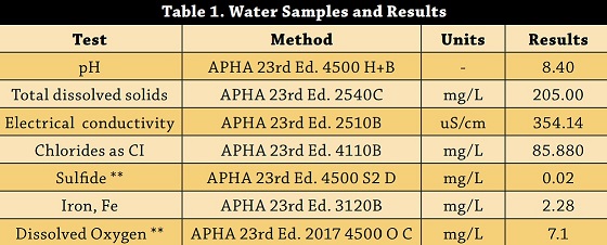
• Water analysis from the line in the second level corridor. The water sample obtained from the line was analyzed to determine if any constituent could contribute to the internal corrosion of the line. The results are presented in Table 1. Moreover, no signs of microbiological activity were detected in the water.
Observations and Conclusions
The piping submitted for analysis displayed significant corrosion. The evidence collected from extensive testing and examination indicates that this is a classic case of failure due to the corrosion under insulation (CUI) phenomenon.
Although the coating complied with the specification requirements, it was noted to be inconsistently applied; many of the locations were having thicknesses well below the specification. This contributed to the under-protection of the metal underneath. Corrosion between the threads has been attributed to crevice corrosion; however, CUI was the primary cause of corrosion in the chilled water application system.
CUI refers to the corrosion of piping and other components resulting from water trapped beneath insulation or fireproofing. It is a widespread issue on insulated carbon steel between -12 and 175 °C (10.4–347.0 °F).
Corrosion rates increase with rising metal temperatures up to the point where water evaporates quickly. While the water boils or steams off above the boiling temperature, 100 °C (212.0 °F), it does not do so instantaneously. It takes some time for water to boil off and for wet insulation to dry out. During this time, the metal corrodes. The higher the temperature above the boiling point, the faster the water will evaporate and the more the insulation will dry out. With a high enough rate of wetting and replenishment of water in the wet insulation, CUI can occur on equipment operating at virtually any temperature of practical concern.
The extent of CUI damage depends on the total duration that the equipment remains wet due to exposure to damp insulation. As a result, while higher operating temperatures will lead to a higher corrosion rate, the overall amount of attack over an extended period may happen at a lower temperature if the metal remains wet for significantly longer periods at a lower temperature.
Typical factors contributing to CUI:
• Poor design or installation of insulation systems that allow water to become trapped will increase CUI.
• Insulating materials that take longer to dry out can be more susceptible to causing extensive CUI.
• Cyclic thermal operation or intermittent service can exacerbate corrosion.
• Damage is worsened by contaminants that may be leached out of the insulation, such as chlorides.
• CUI can be found on equipment with damaged insulation, insulation jacketing, vapor barriers, weatherproofing, or mastic, or where caulking has hardened, separated, or is missing.
• CUI can occur where water enters protrusions through the insulation or at insulation termination points, such as couplers.
• Piping components and locations that are particularly vulnerable include dead legs (i.e., vents, drains, and other similar items), pipe hangers and supports, valves and fittings with irregular insulation surfaces, bolted-on pipe shoes, insulation terminations at flanges or other piping components, insulation terminations in vertical pipes, and the first few feet of a horizontal pipe run adjacent to the bottom of a vertical run.
• Insulation jacketing seams located on top of horizontal piping or improperly lapped or sealed insulation jacketing can result in CUI.
• Locations where moisture or trapped water naturally accumulates due to gravity drainage before evaporating, such as low points in piping runs and insulation support rings on vertical columns.
• Localized CUI can still occur where piping and equipment have been coated beneath the insulation if the coating has deteriorated or been damaged.

Prevention and Suggestions for Mitigation
High-quality, immersion-resistant non-metallic coatings that are properly applied to the surfaces to be insulated can offer long-term protection. Additionally, flame-sprayed aluminum coatings can be used on carbon steels because the coating preferentially corrodes through galvanic action, protecting the base metal.
However, several strategies should be considered for successful installation:
• The best mitigation is achieved by ensuring that a suitable and sufficient coating is applied to the piping before insulation.
• Proper maintenance of insulation, insulation jacketing, sealants, and vapor barriers is crucial in preventing moisture ingress.
• The careful selection of insulating materials is essential. Both water absorption properties and water retention characteristics should be considered. Some insulating materials absorb minimal water but still trap water against the pipe or equipment for extended periods due to slow water removal.
• While closed-cell foam glass materials may hold less water and be less prone to causing CUI, studies indicate that an open-cell structure allows water vapor to escape more quickly, enabling the insulation to dry faster. A faster drying time, corresponding to reduced metal wetting time, should help mitigate CUI.
• Insulation containing added corrosion inhibitors should also be considered.
Editor’s note: This article first appeared in the July 2023 print issue of CoatingsPro Magazine
. Reprinted with permission.